
Start with what the system sees and must answer
People appear to locate a gauge and read it simultaneously, but software must separate these tasks. A correct angle on the wrong instrument still produces the wrong reading point. Verify object location, scale meaning and instrument configuration together.
AI learns appearance from examples; it does not automatically know the unit or business action associated with a dial. Geometry converts positions into angles and values when the actual scale is known. Combining methods makes individual stages and failure causes easier to inspect.
For a linear gauge, establish scale start, end and direction before interpreting the output. The same angle can represent different values on different dials. An illustrated 42 PSI must agree with that scale and needle, not simply be plausible-looking text.
Scroll the diagram horizontally to inspect all details.
1. Separate the tasks before selecting a model
Computer Vision includes several methods, not one algorithm. Detection locates objects, segmentation separates pixels, keypoints locate significant positions and OCR reads text. Gauge pipelines may combine these with conventional geometry, selected from the scale and imaging constraints.
Analog reading can need center, tip and scale endpoints. Digital reading must preserve signs, decimals and units. Correct detection does not establish numerical accuracy. NLP and generative AI are not necessary in every gauge-reading pipeline.
2. Convert geometry into a value with a unit
For a linear scale with a consistent direction and angle wrap already handled, use v = v_min + (theta - theta_min) / (theta_max - theta_min) * (v_max - v_min). Confirm endpoints, sweep, direction and range from the actual dial. Do not apply this directly to logarithmic or piecewise scales.
Perspective changes apparent geometry, and glazing may create a second needle image. Correction requires sufficient reference information. Worn, illegible or uncalibrated instruments retain their own measurement uncertainty even when an image is interpreted correctly.
3. Datasets and reference answers
- Collect shifts, lighting conditions, ranges and instruments, including unreadable observations.
- Document labeling criteria and review disagreements between annotators.
- Split training, validation and test by instrument, camera and day to avoid similar-frame leakage.
- State how reference values and their uncertainty are established; human labels are not automatically correct.
- Fix the test set before threshold tuning and disclose exclusions.
4. Measure correctness and unreadable observations together
MAE averages absolute error. Full-scale error divides error by the scale span and multiplies by 100. Report distributions and worst cases too. Percent error relative to the reference value becomes problematic near zero.
Report detection precision and recall separately from numerical error and invalid rate. State whether denominators include all observations or only accepted ones, with counts by condition. Model confidence is not automatically a calibrated probability of correctness.
5. Deployment and continuing quality checks
- Version the model, preprocessing and scale settings for traceability.
- Measure whole-pipeline latency on the target hardware, not development-machine inference alone.
- Revalidate after quantization, runtime, camera or resolution changes.
- Monitor blur, lighting changes and drift, retaining necessary examples for authorized review.
- Return invalid for unreadable and stale for old data rather than inventing successful values.
- Keep ordinary image reading separate from engineered protective and emergency-stop functions.
An example: accuracy among answered readings is not coverage
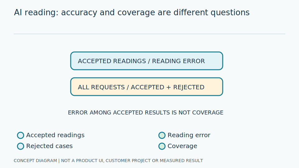
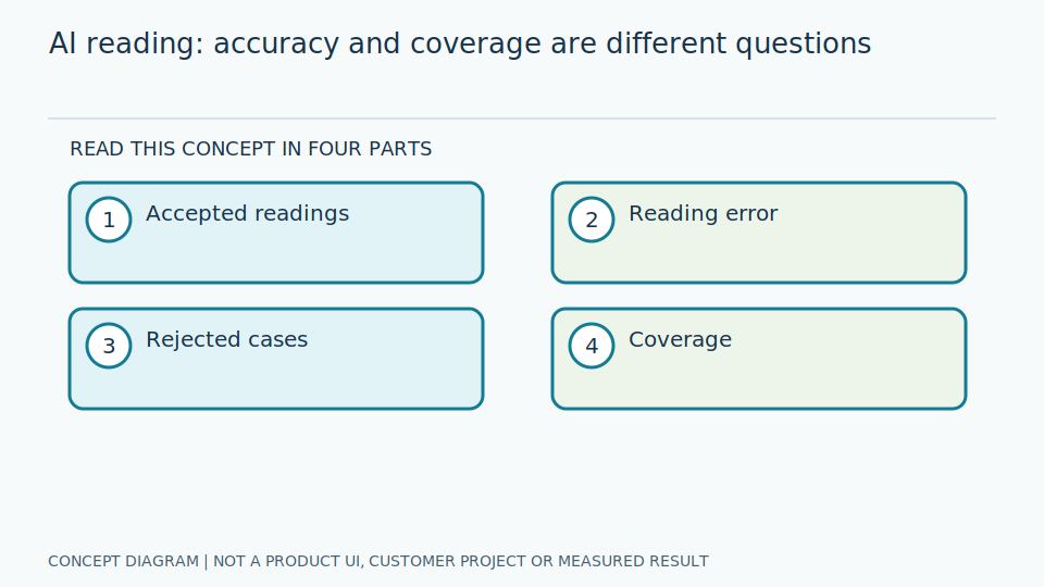
Suppose five images are evaluated and three yield accepted readings with absolute errors of 1, 1 and 4 units. MAE among accepted readings is (1 + 1 + 4) / 3 = 2 units, while coverage is 3/5 = 60%. The other two readings remain invalid; their errors are undefined, not zero. This hypothetical calculation explains denominators, not a product benchmark.
A model confidence of 0.9 does not establish a 90% probability of a correct reading. Probability calibration compares scores with observed outcomes on held-out data, whereas instrument calibration relates a measurement to reference values and uncertainty. Choosing a threshold trades accepted coverage against error; report that trade-off and preserve difficult conditions instead of selecting only favorable accepted cases.
For object or event search, a detector score, image-text similarity and answer fluency refer to different stages. Study vector representations, temporal evidence and evidence-grounded answering separately before combining them. A text answer needs an authorized source and a supported interval; it cannot turn an invalid numerical reading into a valid observation.
Use failures to identify the right improvement
Inspect the image and intermediate outputs before changing models. Correct detection with an incorrect tip may indicate reflection; a correct tip with an incorrect value may indicate direction or range configuration. Versioned settings support reproducible diagnosis.
Do not exclude unreadable observations without explanation. A system answering only easy images may show low error but poor completeness. Report answered quality and unanswered coverage, including the lighting or equipment causing failures.
After changing cameras, optics, runtimes or models, rerun the reference test and add new-condition examples. Keep development separate from evaluation and explicitly identify unsupported conclusions rather than generalizing to every instrument or site.
References and further reading
- Vector representations and similarity
- Time intervals and action evidence
- Answer grounding and abstention
- Model evaluation and uncertainty
- OpenCV: Geometric Image Transformations
- NIST AI Risk Management Framework
- How the gauge-reading pipeline works
- Technology library
- Vision AI Knowledge Library
- Natural-language detection search