
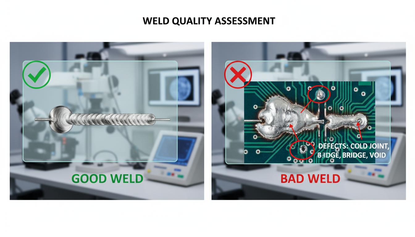
Principles, Scenarios and Suitability
Weld and solder images can show surface shape, presence and visible continuity. Distinguish process types and their acceptance criteria. A uniform-looking seam does not establish penetration depth or internal strength.
Metal welding and circuit soldering serve different functions: a weld may carry loads, while a solder joint may conduct electricity. A bridge is solder connecting positions that should not connect. Smooth appearance does not establish internal joint integrity. Separate visible shape inspection from functional testing, and use requirements for that process rather than borrowing image criteria from another joining task.
Flux assists soldering; its residue may resemble defects. Lighting reduces shadows, but some marks require multiple views, trading coverage for time and location matching. Have specialists define the defect taxonomy and positions needing supplementary inspection before training. Image results should be screening evidence with a stated scope, not a certificate of strength or circuit safety.
Scroll the diagram horizontally to inspect all details.
Illustrative Design Scenario
Illustrative design scenario: inspect solder joints for bridges and missing connections against the board model. Mark areas hidden beneath components as outside the inspection scope rather than inferring a pass from neighbouring visible joints.
Suppose a new board model changes pin positions and adds joints beneath components. Using the old model image could flag a correct position as missing. Confirm the board revision first and separate incompletely visible positions from passed results. Do not fill blind-spot answers from the average results of neighbouring joints.
Operators might add views for visible pins or route hidden positions to another inspection method. Extra angles do not resolve every internal defect. Have reviewers compare images with evidence from supplementary methods permitted by the specification. Use controlled test pieces, not short circuits on operating equipment or strength tests that endanger people.
Inputs and Prerequisites
Prepare weld or solder requirements, inspection locations, expert-confirmed defect images and any necessary supplementary methods, such as X-ray or mechanical testing appropriate to the task.
Record materials, process, part model and specification revision, with positions the camera actually sees. Ambiguous labels need reasoning and a reviewer, not decisions based solely on resemblance to attractive handbook pictures.
Results should identify the inspection position, mark type, image evidence and remaining supplementary checks. Invisible is not the same as no defect. Retain brightness or material changes to explain score changes. Supplementary evidence must belong to the same part and position. Evidence from a neighbouring part does not establish the actual condition of the joint highlighted in the image; reviewers must confirm the association before combining reports.
Trial and Integration Workflow
- 1Separate defects observable at the surface from internal defects.
- 2Arrange lighting to reduce reflections and map locations to the part drawing.
- 3Have reviewers resolve ambiguous results and refer cases for supplementary inspection.
Evaluation and Acceptance Criteria
Measure misses by defect and location across batches, fluxes, materials and production tools. For screening claims, report how many cases still need supplementary inspection. Image results are not evidence of mechanical strength or electrical continuity.
Reserve testing from batches and tools not used for training. Include large marks, borderline marks and good parts with flux residue to reveal false rejects. Do not summarise performance solely from clearly visible defects.
Have specialists inspect samples of passed results and held cases, recording disagreements. Verify drawing-to-position matching after model changes. Being able to read images does not establish that the manufacturing process complies with a standard.
Scroll the diagram horizontally to inspect all details.
Failure Cases and Limitations
Reflective surfaces, smoke and flux residue may resemble defects, while internal voids and joints remain hidden. This article does not set acceptance standards on behalf of welding engineers or certify parts from images alone.
Extending to load-bearing work or critical circuits increases the consequences of missed faults. Review inspection methods against specific requirements rather than treating experience on one board or joint type as proof for every task.
Supplementary inspection belongs to responsible personnel using safe methods. This article does not propose opening equipment or creating defects in actual operation. Standards provide a study framework, not certification of equipment or an already installed internal-inspection capability.
Practical Checklist
- Are defects defined for the actual joining process?
- Are hidden locations requiring supplementary inspection explicitly identified?
- Have specialists approved the proposed acceptance criteria?