
Content Level: Overview / Implementation considerations
Principles and Suitability
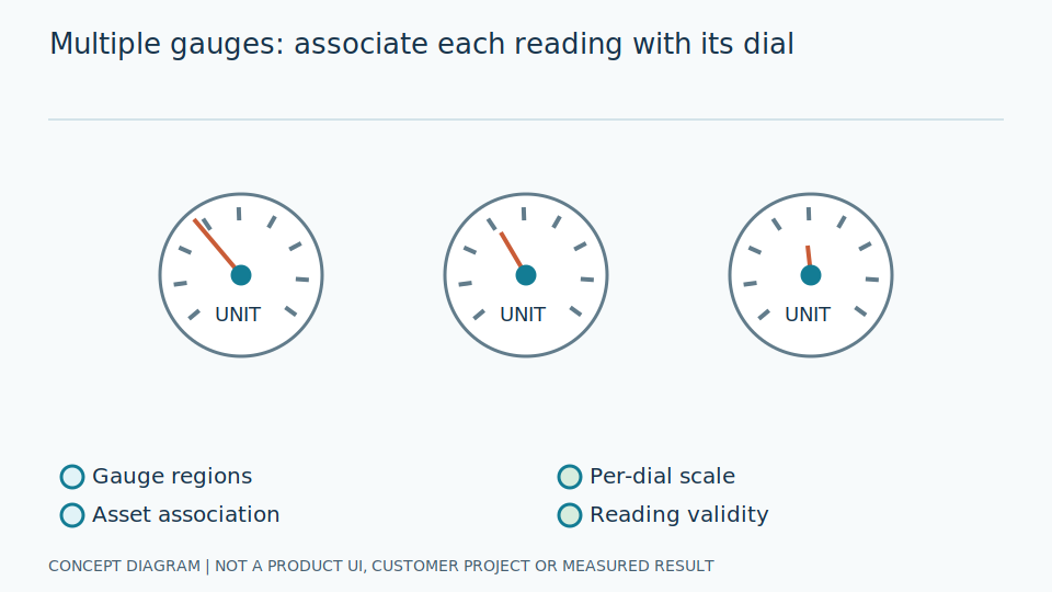
Reading multiple gauges requires separate detection, per-gauge interpretation, and tag assignment. The number of boxes in an image does not establish reading capacity: wider fields of view reduce pixels per gauge, and different gauge types may need different readers. Capacity concerns usable, correctly associated values, rather than merely how many object locations can be proposed in a crowded scene.
Seeing an entire panel is convenient but reduces the image area available for each instrument. Inspect the smallest and farthest gauge, not just a prominent central one. A tag is an equipment identifier in the data system, distinct from detection-box ordering. Each result must establish what was read, which instrument it belongs to, and whether units are visible. Many boxes do not prove that every value is adequate or correctly named.
Engineers separate detection, type-specific readers, and verified position-to-tag mappings, with calibration for each gauge. Tiled-image coordinates must be mapped back before cropping original images, rather than passing detail-poor thumbnails into reading. Define per-tag states for not detected, unreadable, and stale data. A neighboring gauge's value or a previous reading must not silently replace missing evidence just to produce a complete-looking panel record.
Scroll the diagram horizontally to inspect all details.
Illustrative Industrial Example
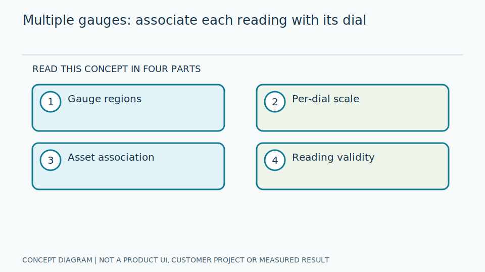
Design example: a panel contains pointer gauges and digital displays. Crop each instrument and associate it with a verified asset tag, returning values, timestamps, and per-tag statuses instead of copying readings between gauges. The design preserves equipment identity and distinguishes different reader requirements, so an apparently valid number is not accepted without checking the instrument and time it describes.
Suppose one gauge is obscured while its neighbor remains visible. Do not shift tags according to the remaining detection order: correct values could acquire wrong equipment names. Preserve verified locations and mark the missing instrument. Panel replacement or camera movement requires mapping review, not forced nearest-neighbor association without acceptance criteria. Reviewers should see tags overlaid on images before using the combined panel readings for interpretation.
Engineers test missing instruments and reordered detections, using appropriate answers for pointer and digital readers. Check per-value times and mapping versions in exported results. Readings drawn from different frames must disclose their timing differences rather than claim simultaneity without capture-time evidence. Verify that missing entries retain explicit statuses at the destination, rather than copying the latest stored values to make the display appear complete.
Study and Trial Workflow
- 1 Survey the smallest or farthest gauges and measure the details visible to the camera.
- 2 Verify ROI-to-tag mappings and choose readers and calibration for each instrument.
- 3 Test missing, obscured, and moved gauges without allowing identities to switch.
Evaluation and Metric Definitions
Report coverage and reading error per gauge, complete-panel correctness, per-tag data age, and per-machine capacity under the actual stream count. An average over available readings can hide an instrument that is consistently unreadable. Evaluation must therefore count the gauges that should have been read and the panels that genuinely contain all required results, rather than considering only successful detected boxes.
Show counts and errors by tag, plus the proportion of complete panels meeting criteria. Coverage needs a denominator based on expected instruments, not just detections. Data age should use trustworthy capture times. Complete-panel results reveal how often tasks needing multiple readings together have adequate information. This distinction matters when individually good results do not arrive together or when one difficult instrument repeatedly prevents a complete decision.
Engineers separate detection, reading, and naming errors using box-and-tag overlays and per-instrument answers. Measure resources with concurrent streams, including waits for the slowest gauge. Added gauges require retesting; do not multiply capacity from a single-gauge image. COCO-style evaluation helps assess boxes but does not establish correctness of every panel value or confirm that a product already supports a particular number of instruments.
Limitations and Failure Cases
Adding gauges without increasing image detail degrades reading. Outputs from different frames should not be called synchronized without known capture times. A convenient wide view does not create additional readable scale markings, needle edges, or decimal points, and a collection of individual values does not automatically describe one shared instant simply because they are displayed in the same table.
Different gauge types need different criteria: a small dial may have units near its edge, while a digital display may contain a thin decimal point. Define type-specific boundaries and do not treat high detection confidence as proof that all readers are ready. Wrong tag assignment matters even when the number is correct. When panels change, return unconfirmed states and inspect locations rather than force a complete table.
Multiple cameras improve detail but add synchronization and maintenance work; one image simplifies acquisition but limits visibility. Balance timing needs and required detail, without claiming capacity from untested examples. This is a multi-instrument design, not confirmation of current product camera counts, gauge counts, reader types, or automatic tag assignment. Missing values must not be interpreted as normal process values or quietly replaced to conceal insufficient evidence.
Practical Checklist
- Are every instrument’s units and pointer or display visible?
- Does a missing gauge return no-read rather than a retained old value?
- Are mapping versions and per-value times provided?