
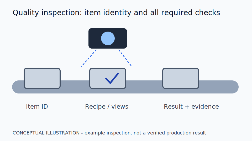
Principles, Scenarios and Suitability
Quality inspection begins with defect definitions and product requirements that images can actually assess. Classification, defect localisation and dimensional measurement need different criteria. Allow uncertain results and a reinspection route rather than forcing every image into a pass or fail decision.
A defect is a failure against the product criteria, not every spot differing from a sample picture. A mark on a decorative part and one on a mating surface can have different consequences. Begin by asking what function the mark affects, then whether the model can see it. External visual inspection should include a hold-for-review state near acceptance boundaries.
A defect taxonomy gives inspectors shared categories and language. Define location, size and severity with boundary examples. Greater sensitivity can hold more good parts; lower sensitivity can send defective parts downstream. The quality owner must choose that trade-off according to product risk, not because a combined score looks high.
Scroll the diagram horizontally to inspect all details.
Illustrative Design Scenario
Illustrative design scenario: a fixed-lighting station photographs surfaces to inspect scratches. Reviewers label severity against product requirements, distinguishing genuine defects from dust or removable marks before designing the sorting process.
Suppose reflections from a glossy part resemble scratches. Operators could add a camera angle or use diffuse lighting. An extra view reveals more surface but increases time per part; diffuse light may obscure shallow scratches. Trial both using reference parts confirmed by inspectors rather than choosing from a single attractive photograph.
For an ambiguous mark, review the image and physical part under the quality procedure. Record whether it is a defect, dust or a shadow, then refine the labelling guidance. Before considering future automatic sorting, verify that results identify the same physical part and provide a hold route when images are incomplete. Do not begin by operating the live sorter.
Inputs and Prerequisites
Prepare drawings, good and bad samples by defect type, images from multiple batches and reviewer criteria. Define camera placement, the image area occupied by the smallest defect, and how each part is identified.
Link images to product model, batch and reviewed labels. Undecided parts must not become good examples merely because no obvious mark is visible. A drawing specifies geometry and inspection locations; it is not a promotional product photograph.
Results should identify defect type, location, image evidence and pass, hold or fail status. Confidence scores are not defect dimensions and do not replace acceptance criteria. Retain the criteria version so a later reviewer can explain why a particular decision was made.
Trial and Integration Workflow
- 1Define a defect taxonomy and check agreement between labelers.
- 2Split datasets by batch or production day, keeping near-duplicate images out of different splits.
- 3Run in shadow mode and review incorrect results before considering integration with a sorting mechanism.
Evaluation and Acceptance Criteria
Report escaped defects and false rejects by type, with sample counts. Test at actual line speed, including image acquisition and actuation time. Acceptance must include ambiguous parts and human reinspection rather than relying on aggregate accuracy dominated by good parts.
A defect escape is a bad part passed; a false reject is a good part rejected. Measure both alongside the hold rate. Separate batches between training and testing so repeated images of the same part do not make performance appear better than it is.
Inspectors should sample passed parts as well as held ones. Reviewing warnings alone cannot reveal escaped defects. Record counts by defect type and disagreements between reviewers, identifying conclusions still lacking sufficient evidence rather than concealing uncertainty in an overall accuracy figure.
Scroll the diagram horizontally to inspect all details.
Failure Cases and Limitations
Surface images do not reveal internal defects or invisible material properties. Lighting and tooling changes can alter results, and new product models require reassessment. Part acceptance remains governed by the quality system of the organisation using the inspection results.
A changed mould or coating can alter the appearance of acceptable parts, increasing warnings without a true quality decline. Inspect physical examples before adding them to the reference set, otherwise a genuine defect may be learned as normal production appearance.
Image inspection does not replace functional or material tests required by the specification. Extending coverage to a new defect is an investigation proposal, not an installed capability. Someone authorised by the quality process must approve the criteria before they determine acceptance of real products.
Practical Checklist
- Does each defect type have examples at the acceptance boundary?
- Does the holdout set come from batches not used for training?
- Is there a reinspection path for unreadable parts?