
Content Level: Overview / Implementation considerations
Principles and Suitability
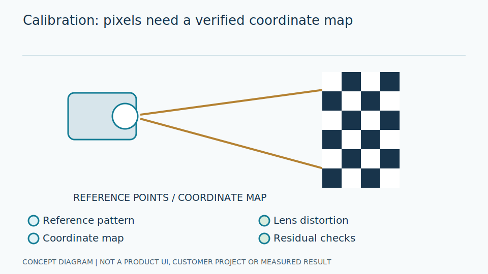
Camera calibration estimates intrinsics and lens distortion, while extrinsics specify camera pose. A homography applies to a plane under appropriate assumptions. These differ from gauge-scale calibration, which maps needle angles to displayed values. Keeping the geometrical and scale questions separate prevents a good camera fit from being mistaken for proof of correct measurement.
Image calibration explains how image positions relate to the viewed object; it does not make a gauge measure correctly. Intrinsics describe internal camera properties, and extrinsics describe position and orientation relative to a reference frame. Lens distortion can bend lines or dial boundaries. Distinguish that from a tilted dial caused by viewpoint, since these effects require different correction methods and assumptions.
A homography transforms between planes under specified conditions, so check whether reference and reading points occupy suitable planes. Engineers store camera parameters separately from scale mappings. A replacement gauge may require a new scale even with the same camera; changed focus or camera angle may require renewed image assessment while the scale remains valid. Bind versions to equipment and images to preserve this distinction.
Scroll the diagram horizontally to inspect all details.
Illustrative Industrial Example
Design example: correct an oblique dial view before locating the pivot, then establish reference angles from several scale marks. A nonlinear gauge needs a mapping based on its scale, not an estimate using only two endpoints. Making a dial look circular is not sufficient evidence that needle angles now map to the correct displayed values.
Suppose marks have unequal angular spacing. Linear interpolation between minimum and maximum may produce correct endpoints but incorrect intermediate values. Collect references along the scale and define justified interpolation. If some numbers are invisible, do not infer mapping from a similar-looking dial without confirming model and unit. A visually pleasing geometrical correction does not itself establish the meaning of needle position.
Engineers verify transformations using independent points excluded from parameter fitting, then inspect the corrected pivot and needle against the original image. Test intermediate values with reference answers, specifying units and increasing direction. After changing the region of interest, check coordinate conversion and image size compatibility. Formulas can be tested with simulated data without manipulating an instrument in a live process to obtain desired values.
Study and Trial Workflow
- 1 Capture calibration-target images at multiple positions within the operating field of view.
- 2 Inspect reprojection error and independent images after distortion correction.
- 3 Define scale mapping and test intermediate values, recording the calibration version.
Evaluation and Metric Definitions
Use reference values at multiple angles to measure reading residuals and uncertainty. Low reprojection error does not establish correct pressure. The camera-model fit and downstream reading have different meanings and units, so report and interpret them separately rather than using success in a geometrical subtask to substantiate the entire measurement.
Reprojection error compares image points with points projected back by the model; reading residual compares a reading with its reference answer. A camera model fitting calibration points well may still be inappropriate for a dial on another plane. Check downstream results and uncertainty components rather than allowing one subtask's metric to guarantee overall measurement correctness without evidence at the reading level.
Engineers inspect errors by angle and image position to expose pivot bias or remaining distortion. Use independent images and state reference-point counts. Verify that parameters match the lens, focus, and evaluated image dimensions, and disclose reference uncertainty. Selecting a calibration method from documentation is a design decision, not evidence that the system has received standards certification or that the reference itself is exact.
Limitations and Failure Cases
A homography cannot fully correct parallax between a needle and scale on different planes. Moving the camera, changing focus, or replacing the gauge may invalidate calibration. Parameters therefore need an explicitly maintained scope, rather than being reused indefinitely just because the software continues producing apparently continuous values without an obvious processing error.
When a needle stands above the scale, rectifying the dial plane leaves a viewpoint difference for the needle. Assess mounting constraints and reading uncertainty instead of assuming more calibration points solve every plane. References concentrated in a small area may not reveal boundary errors. Evaluate the actual scope and do not extend conclusions beyond distances or angles supported by the available evidence.
Detailed calibration adds collection and maintenance work but helps trace discrepancies. Define review triggers, such as camera movement or housing replacement, and checks for continued parameter validity. Quietly reusing old versions can preserve apparent continuity while changing meaning. Show an unready-to-read state when configuration is unconfirmed. Image calibration does not certify the gauge's own measurement accuracy or the safety of downstream decisions.
Practical Checklist
- Does the reference include its unit and origin?
- Are the conditions that trigger recalibration defined?
- Are parameters stored with their images and equipment?