
Principles and Suitable Contexts
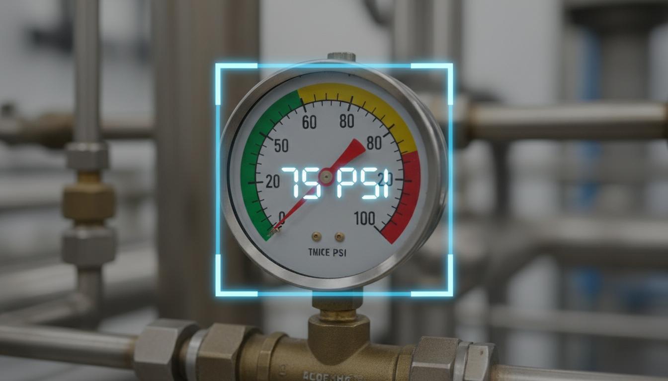
Locate the dial centre, pointer tip and reference marks, then map the pointer angle to the scale. This is suitable for clearly visible, fixed dials. A linear scale may use two reference points; a nonlinear scale needs multiple reference marks. Do not apply one mapping to every dial.
Think of the pointer as a position indicator, not the number printed nearest to it. Select the scale ring and direction of increasing values first, then identify the marks surrounding the pointer. Interpolation estimates the proportion of distance between those marks; it does not increase the instrument's resolution. Report only the numerical detail that the visible graduations can reasonably support.
Geometric correction can make an angled dial image appear straight, but the pointer and graduations may occupy different planes, leaving viewing error. Retain the centre coordinates, reference marks and transformation version for later inspection. After remounting the camera, verify the angle-to-value relationship rather than immediately reusing its old settings. A corrected-looking image alone does not establish that the geometry remains valid.
Scroll the diagram horizontally to inspect all details.
Data and Preparation
Collect images with independently checked readings and units. Record the measurement range, smallest graduation, dial model and pointer rest position. Position the camera close to perpendicular to the dial and check reflections and pointer-tip resolution. Include several values across the range, not just normal operation.
Begin with images whose graduations and units a recorder can identify without guessing. Mark the chosen scale ring and explain the selection on dual-unit dials. Include the pointer crossing numbers, positions near thick marks and different daylight conditions. Obtain these examples during ordinary operation; do not manipulate the process simply to move the pointer to a desired training position.
Keep enough reference marks within the image boundary to detect camera movement. Cropping down to the pointer alone removes that check. Balance resolution against storage by checking whether the tip and minor graduations remain distinguishable. Before use, ask another reviewer to compare the image with the physical dial, and register camera-angle or lighting changes as changes to the reading conditions.
Failure Cases and Limitations
An oblique view introduces parallax, a counterweight can be mistaken for the pointer tip, and a dual-unit dial can lead to reading the wrong scale. Shadows or condensation should produce an unreadable result rather than a guessed normal value. Accurate image reading does not establish that the gauge is calibrated.
When a reading jumps, examine the source image before concluding that pressure or another measured quantity really changed. Separate an obstructed pointer, an incorrect centre, the wrong scale and genuine movement as possible causes. A rate-of-change check can flag readings for review, but forcing every sequence to remain smooth may erase the very event the user needs to observe.
Pointer vibration may reflect both machine vibration and process variation. A long exposure can combine several positions into one thick line. Mark that observation as uncertain and retain an image sequence for responsible personnel to inspect. A mechanically defective gauge can produce consistently misleading image readings, so keep instrument inspection separate from camera checks rather than interpreting consistency as proof of correct measurement.
Scroll the diagram horizontally to inspect all details.
Evaluation Methods
Separate test data by gauge and capture day. Compare readings against two reviewers using an agreed procedure. Report mean absolute error in engineering units, maximum error and rejected-image proportion. When using a calibrated reference, distinguish the gauge error from the additional error introduced by reading its image.
Mean absolute error, or MAE, averages the size of differences without their signs. It is easy to interpret but does not show a persistent tendency to read high or low. Examine signed differences too, grouping results by scale ring, angular region and lighting. Keep images on which reviewers disagree as ambiguous cases; do not force a reference answer just to improve the score.
Tie acceptance criteria to user decisions, such as the difference requiring a second human reading, and state the units and tested range. Evaluate images never used to adjust pointer detection, counting rejected images in the full dataset denominator. Metrology guidance helps distinguish sources of uncertainty; citing it is not evidence that either the instrument or the image-reading system has received certification.
Review Checklist
- Confirm the unit and selected scale.
- Test both range endpoints and any angular wraparound.
- Retain unreadable images with rejection reasons.
- Define readings that require human review.
References and Further Reading
References explain principles, not product certification. Requirements from another jurisdiction do not automatically replace local requirements or the actual equipment manual.